1 Introduction
1.1 Document Overview
The purpose of this document is to describe the deployment of the Cisco ISE cluster for the Rubin Observatory on a high-level, as a way for our collaborators to understand how authentication, authorization, and accounting (AAA) will be performed in the Chilean project networks towards operations, without compromising the security of the cluster configuration itself, based on the requirements set by the project, especially -but not limited to- the Tiger Team in different ICDs and in the documents mentioned in section 1.4.
After acceptance this document may or not be under change control, and regardless of that this is considered a living document that will be updated upon requirement addition or changes, experiences in the deployment, and operations process.
1.2 Scope
- Deliver a high-level overview of the Cisco ISE deployment.
- Deliver enough details to allow readers to understand how authentication, authorization, and accounting work for the Rubin Observatory networks, without compromising internal security.
1.3 Assumptions and Caveats
- It is assumed that low-level configurations for this cluster are considered sensitive as defined in LPM-122 and therefore not shown publicly here. For management-approved project members, details can be found in Confluence.
- It is assumed all the project concepts derived from other documents such as those mentioned in section 1.4 and/or the associated ICDs, are correct and remain unchanged.
- It is assumed the reader is familiar with concepts such as authentication, authorization, accounting, mac address bypass, x.509 certificates, 802.1x, and LDAP trees.
2 Technical Solution Overview
2.1 Context
As of early 2017, the network infrastructure in La Serena was very basic and intended for end-users, internet, and minor intranet access. Authentication and Authorization (AAA) was done manually by the IT North group, authorizing specific machines on specific network ports for wired access, and using 802.1x enabled Wi-Fi SSIDs synced with the Active Directory’s LDAP user accounts; no fixed PSKs were used. In contrast to other transition IT services such as VoIP and network infrastructure, CTIO CISS’s did not provide support for AAA services.
As part of technical analysis of the project requirements by several vendors and distributors held in the 2015/2016 timeframe by the Tiger Team, out of which Cisco Systems was the chosen vendor for all the LAN network infrastructure, including AAA, the Cisco Identity Service Engine (ISE) solution was the specific technical solution chosen for the project.
As the Rubin Observatory telescope building and the new base facilities get ready, the following summary requirements must be fulfilled by the AAA infrastructure to be implemented:
- The solution must be redundant, distributed, and highly available.
- The solution must allow flexibility to perform authentication for systems using MAB, 802.1x, open-conditional access based on the request source device and/or location at least. Using internal or external authentication sources, mainly LDAP-based.
- The solution must allow flexibility to perform authorization for systems based on attributes such as internal or external identify source, usernames and/or groups, called-station IDs, device origin/manufacturer/type, at least, and be able to apply differentiated services including -but not limited to- dynamic ACLs, static VLAN assignments via Radius attribute overrides, voice domain identification, web-redirection for self-registration and/or remediation.
- The solution must allow accounting for radius events and TACACS events, in the case of Cisco network devices. Network devices using TACACS for AAA must be able to access the same levels of AAA as stated in points 2 and 3, plus accounting based on authorizations profiles (read-only, read-write, or custom permissions) which shall record logins and every command applied to the devices associated with the solution.
2.2 Cisco ISE (Identity Service Engine)
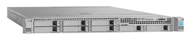
The Cisco Secure Network Server is based on the Cisco UCS C220 Rack Server and is configured specifically to support the Cisco Identity Services Engine (ISE) security application.
Granting and denying network access has evolved beyond simple user name and password verifications. Today, additional attributes related to users and their devices are used as decision criteria in determining authorized network access. Additionally, network service provisioning can be based on data such as the type of device accessing the network, including whether it is a corporate or personal device.
The Cisco Secure Network Server is a scalable solution that helps network administrators meet complex network access control demands by managing the many different operations that can place heavy loads on applications and servers, including:
- Authorization and authentication requests
- Queries to identity stores such as Active Directory and LDAP databases
- Device profiling and posture checking
- Enforcement actions to remove devices from the network
- Reporting
There are different operating modes for the chosen solution in regards to deployment options, both with pros and cons; this document will expand on this matter in section 3.5.
Please note that the first purchase for Cisco ISE cluster (for the Summit site) was done in mid-2017, with the devices arriving at La Serena around September of the same year, when neither the summit nor the base sites were ready to perform the installation of the appliances. During this time until the procurement of the second part of the cluster (for the Base site) early in 2019 these appliances were installed and used at the Summit site but this specific model, the Cisco ISE 3515 appliance, went out of sale and we had to purchase its replacement model. The cluster was reseated and redeployed when the Base site was ready for operations in January 2020.
The specific device models are the following:
- Secure Network Server SNS-3615-K9: NAC controller, intended for administration and monitoring purposes, based on a Cisco UCS 220 M5 server modified with dual 10G NICs and a specific CPU/RAM/HDD setup to support up to 10000 endpoints.
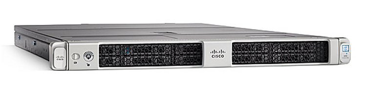
- Secure Network Server SNS-3515-K9: NAC controller, intended for policy enforcement, based on a Cisco UCS 220 M3 server modified with dual 10G NICs and a specific CPU/RAM/HDD setup to support up to 10000 endpoints.
3 Defined AAA Architecture
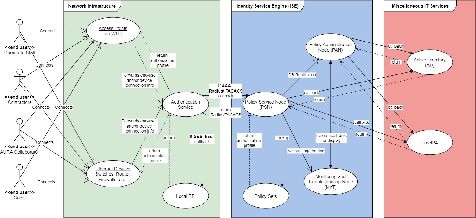
3.1 Logical Design
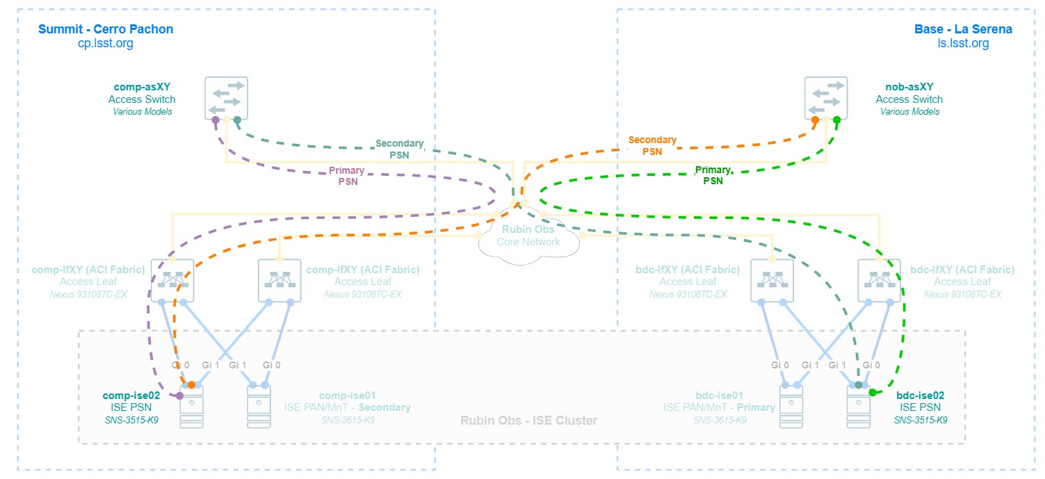
3.2 Physical Design
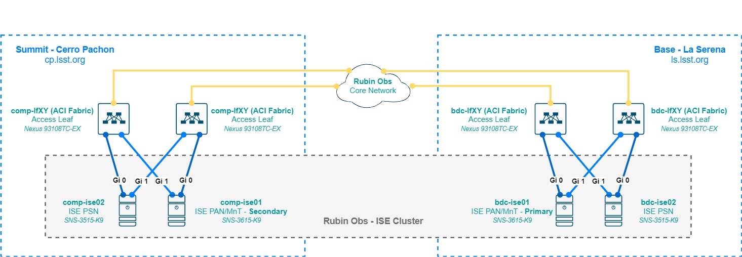
The Cisco ISE appliances DO NOT support link aggregation via LACP, only an active/standby NIC bonding, This is created automatically by the base operative system when in the configuration the main NIC is configured to have a backup (e.g. in this case Interface Gi1 is backup to Gi0). For 3615 appliances that have up to 6 NICs, 3 bonding groups are created.
3.3 Redundancy and High-Availability
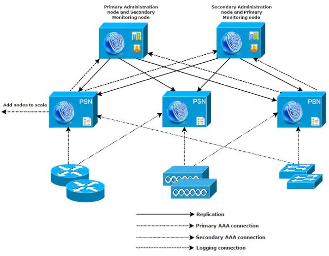
Given the requirements, the chosen solution, and the design considerations, a distributed medium-sized network deployment was chosen. Not specific to this deployment but to any Cisco ISE installation, the service defines node types or personas, which perform different functions, being the main ones:
- Policy Administration Node (PAN): Administration node that provides full access to the graphic interface for the deployment configuration. Replicates the configuration DBs across nodes and queries reference data from the MnT node for displaying it to the system administrator.
- Monitoring and Troubleshooting Node (MnT): Monitoring node that collects logs for accounting for the whole deployment to later serve the PAN node.
- Policy Service Node (PSN): Node that enforces the service policies (represented but policy sets) for authentication, authorization, and accounting. This is the node that interacts with the network devices using Radius and/or TACACS.
As seen in the diagram at section 3.2, in a distributed medium-sized deployment the personas are split in different physical nodes, there’s a pair of 3615 appliances serving as PAN and Mnt on a Primary (La Serena) and Secondary (Cerro Pachon) role setup, and a PSN node at each site. The PAN/MnT nodes ensure that the service is always available by replicating its configuration database across the nodes in the deployment, and redundancy is achieved by configuring each network device for AAA pointing to both PSN, both for Radius and TACACS, giving always priority to the local PSN of its site (e.g. a Cerro Pachon switch will always have comp-ise02 as its preferred PSN).
3.4 Scalability
Scalability is achieved by adding mode PSN nodes to the cluster, for instance, we could eventually add a policy cluster for the Tucson site and allow AAA services to be provided in those networks, or eventually absorb the policy nodes, however adding mode PSN nodes does not add capacity to the deployment in terms of endpoint capacity. The 3615 and 3515 appliances are sized for 10000 concurrent authenticated endpoints, which is more than enough considering the size of the project, potential inclusion of a PSN for the Tucson site, and eventually a merge with NOIR Lab, at least for the Chilean sites.
Licensing scales in tiers, being the Base license a perpetual entitlement for basic AAA, MAB, 802.1x, guest services, etc…Then comes the Plus license which enables BYOD capabilities and profiling, among others, and the Apex license which enables posture and third-party integrations. Plus and Apex are subscription-based (1, 3, or 5 years) and these always consume a base license first. Licenses are consumed dynamically based on active sessions, meaning when an authenticated endpoint ends its session, the license is released for reuse by other endpoints.
This is just a primer on Cisco ISE licensing, for more information please visit the Licensing section of the Cisco ISE Administrator Guide.
3.5 Design Considerations
- 300 ms of RTT is the maximum acceptable latency between the PSN and the PAN/MnT nodes for a distributed environment. This shall be considered if the Tucson site needs to be annexed to the Rubin Obs ISE cluster with a local PSN node, and/or in the case of a merge with NOIR Lab for the networks in the Hilo site.
- There can be only 2 PAN/MnT nodes per medium-size distributed deployment (also called hybrid-distributed deployment) with several PSN nodes. Usually for a distributed deployment companies keep both of these nodes in the main location and only provide remote locations with PSN nodes. In the case of Rubin Obs, to give the Summit site autonomy during an outage considering that AAA may include mission-critical devices, the secondary PAN/MnT node is installed there, to transition to primary in such case to keep services running. To improve this setup, a local Active Directory domain controller and a Free IPA node must be available at each site.
- Admin access to the primary PAN/MnT is controlled via LDAP group attributes, with local admin accounts only as a backup. Accounting for configuration changes is enabled and logged.
- Any administration, including configuration changes and log auditing, is done via the primary PAN/MnT, any other nodes provide a restricted graphic interface. This node must be available whenever possible given a major network failure.
- Network devices must be configured for redundant Radius and TACACS groups pointing to their local PSN node as stated in section 3.3.
3.6 Security
Cisco ISE provides security services for AAA by design and can, therefore, integrate not only with external identity sources such as Active Directory or Free IPA but also to other platforms such as Cisco Umbrella, Stealthwatch, Firepower appliances, etc… and perform special traffic redirects for web authenticators, agent enforcement such as Cisco Anyconnect for posturing services, etc… From this considerably large range of options, for the sake of simplicity and to cover the baseline requirements, these are the security features to be implemented as a baseline.
- Device Admin Policy Set - TACACS: Used for network device AAA. Considers attributes such as site, device type, operative system, incoming authentication protocol and/or specific attribute, etc… and returns an authorization profile with specific permissions.
- If incoming authentication request equals a username in an internal or external identity source with an attribute relatable to read-only. Authorize a shell profile allowing only system visualization.
- If incoming authentication request equals a username in an internal or external identity source with an attribute relatable to read-write. Authorize a shell profile allowing full system control.
- Else, deny access.
- Regular Policy Set - RADIUS: Used for endpoint AAA. Considers attributes such as site, endpoint type, internal or external identity parameters or grouping, incoming authentication protocol and/or specific attributes, etc… and returns an authorization profile with specific permissions.
- If incoming authentication request equals a RADIUS port-type Ethernet AND flow type is 802.1x or MAB, query internal and external identity sources for parameters such as device type or grouping, username or computer grouping, and authorize a profile with the corresponding level of access according to the nature of the incoming request, placing the endpoint in the correct network segment.
- If incoming authentication request comes from a wireless network device AND flow type is 802.1x, query external identity sources for parameters such as device type or grouping, username or computer grouping, and authorize a profile with the corresponding level of access according to the nature of the incoming request, placing the endpoint in the correct network segment.
- Else, deny access.
These policy sets are described on a very high-level as these are considered sensitive according to LPM-122. For management-approved project members, details can be found in Confluence.
3.7 Monitoring
The monitoring is done initially by the cluster itself in the PAN/MnT nodes, which are SNMP trap and Syslog collections on itself for the network devices authenticating with the cluster via the PSN nodes; syslog and SNMP traps coming from the network devices are also used in processes such as profiling.
To monitor the cluster nodes themselves, a limited SNMP implementation using specific read-only MIBs is available to keep track of the hardware health. Options are not broad as with other network devices or with a regular service but depending on the level of granularity needed by the System Administrator in conjunction with the Network Engineer, the following link summarizes the SNMP monitoring options for Cisco ISE exhaustively.
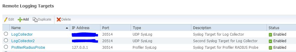
As mentioned before, the PAN/MnT nodes are Syslog collectors themselves, but external collectors are possible to be configured as well. Be aware that depending on how many endpoints are authenticating with the PSNs, plus if accounting services are enabled for TACACS, logging can get very process and bandwidth-intensive, therefore please check the local logging statistics in the PAN/MnT nodes before committing to log externally to ISE.
Custom scripting using SSH and the ISE API is also acceptable given the use-case, as well as the use of software abstraction layers that can query the PAN/MnT primary node via API or CLI and present that information to other services or databases.
3.8 Management
Cisco ISE is a provides management access to network devices via TACACS or RADIUS, and other custom RADIUS authentications can also be set up in ISE for devices such as Services (there are other more specialized services for that though), but management for the ISE cluster itself can be done in-band via the graphical interface or SSH, and out-of-band via the Cisco CIMC. Some other options may be available but the following were be implemented as the baseline:
- In-band management access to the cluster is done via the Primary PAN node, synchronized with the local domain controller of the site, and implementing differentiated levels of access. For IT network administrators, the regular domain account shall provide read-only access and the admin domain account shall provide full access to the controller. Local admin accounts can be kept to avoid lockouts upon major network failures and the local domain controller is not available.
- IPMI/BMC access is provided by the onboard Cisco CIMC hardware, also placed in a different and more protected network than in-band management.
4 Appendix
4.1 Terminology and acronyms
| Term | Meaning |
|---|---|
| AAA | Authentication, Authorization, Accounting |
| ACL | Access Control List |
| AD | Active Directory |
| API | Application Programming Interface |
| AURA | Associated Universities for Research in Astronomy |
| BMC | Baseboard Management Controller |
| BYOD | Bring Your Own Device |
| CIMC | Cisco Integrated Management Controller |
| CISS | Computing Information Services South |
| CLI | Command-line interface |
| CTIO | Cerro Tololo Inter-American Observatory |
| DB | Database |
| HA | High Availability |
| HDD | Hard-Drive Disk |
| ICD | Interface Control Document |
| IEEE | Institute of Electrical and Electronics Engineers |
| ISE | Identity Service Engine |
| IT | Information Technology |
| IPMI | Intelligent Platform Management Interface |
| LACP | Link Aggregation Protocol |
| LDAP | Lightweight Directory Access Protocol |
| MAC | MAC Authentication Bypass |
| MIB | Management Information Base |
| MnT | Monitoring and Troubleshooting Node |
| NAC | Network Access Control |
| NIC | Network Interface Card |
| NOAO | National Optical Astronomy Observatory |
| OOB | Out of band |
| PAN | Policy Administration Node |
| PSN | Policy Service Node |
| RADIUS | Remote Authentication Dial-In User Service |
| SNMP | Simple Network Management Protocol |
| SSH | Secure Shell |
| TACACS | Terminal Access Controller Access Control System |
| VLAN | Virtual local area network |